You need to make a shape to create a line type, but first you'll have to create the shape using polylines.
Start a new drawing using the New Drawing symbol on your quick access toolbar, at the top left of your screen right next to the big A symbol.
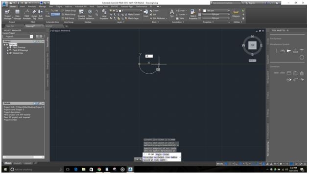
Type PLine to start the polyline command. Type 0, 0 then ENTER for the starting point; type "A" then ENTER to draw an arc; drag the cursor to the right and type .09 then ENTER

Again drag the cursor to the right and type .09 then ENTER; you should have a poly line that looks like this:
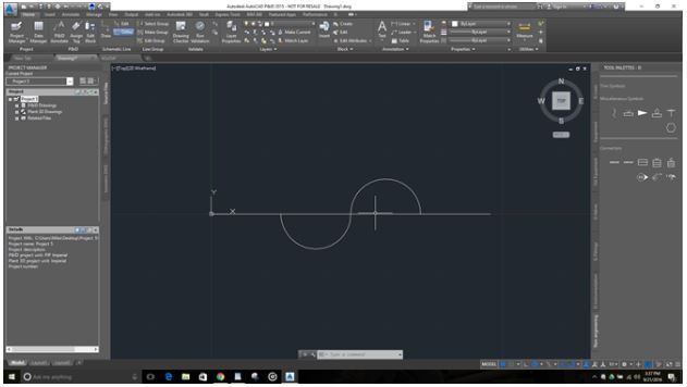
Select the Polyline and type MOVE, move the poly line to the right and type .09 then ENTER.
Start a new Polyline by using the PLINE command; type 0,0 then ENTER; drag the cursor to the right and type .36 then ENTER; you should have 2 polylines that look like this:
Now you need to turn this into a shape file. Type the command MKSHAPE then ENTER; find an easy place to locate this shape file like the desktop and save it as ElectroMagnetic.shp; back in AutoCAD type ElectroMagnetic for the name then ENTER; Since this shape file has curves type 512 for the resolution then ENTER; type 0,0 then ENTER for base point; select both of the created polylines then ENTER.
Now you need to insert that shape file. Type SHAPE then ENTER; type the shape name which is ElectroMagnetic then ENTER; type 0,0 then ENTER for base point; then hit ENTER which leaves the scale at 1.0000; type 0 then ENTER for the rotation angle.
Now that the shape file is inserted we can create a line type. Type MKLTYPE then ENTER; save this file to the same location as the shape file with the same name "ElectroMagnetic"; back in AutoCAD type ElectroMagnetic then ENTER for the name; leave the description blank and then ENTER; type 0,0 then ENTER for the starting point; drag the cursor to the right and either type .36 then ENTER, or select the end point of our shape; select our shape then ENTER.
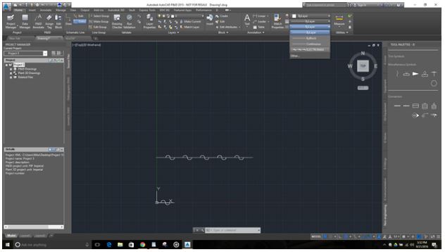
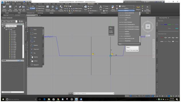
Now the ElectroMag line type exists in this drawing.Start the LINE command and create a long line anywhere in the drawing; select the line then navigate to the properties portion of the ribbon, select the linetype drop down menu as shown below and select ElectroMagnetic:
Now we need to put both the .shp and .lin files you created in the correct location (by creating a line type you should also notice a new .shx file where you saved the .shp and .lin files). Open Windows File Explorer; Navigate to the following location C:\ProgramFiles\Autodesk\AutoCAD 2015\PNID\en-us (if you're using a newer version of AutoCAD be sure to select that folder instead of AutoCAD 2015); You'll copy and paste .shp, .lin, and .shx files into this location.
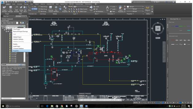
Now you need to create the new ElectroMagnetic signal line in your p&id project setup. First select the lines pallet, located on your tool pallets. Now open your p&id project, in the project manager right click the project title and select Properties from the drop down list:
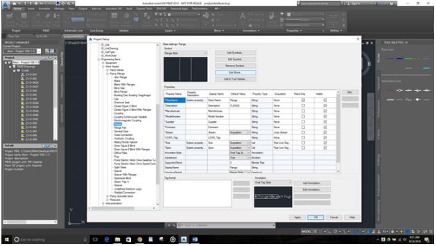
Expand P&ID DWG settings, expand Engineering Items, expand Inline Assets, expand Piping Fittings, select Flange, then in the Flange settings choose Edit Block as shown:
On the Edit Block screen, navigate to the Home tab at the top of the ribbon, navigate to the Properties tab on that Ribbon, select the drop down menu for Linetype, at the bottom of that list select Other:
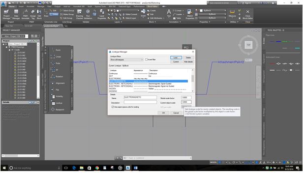
On the next window select Load, in the next window select File, navigate to the location I that I had you put your new linetype in C:\Program Files\Autodesk\AutoCAD 2015\PNID\en-US, select your ElectroMagnetic Line type then select Open. In the next menu scroll down and select ElectroMagnetic then select Ok, In the next window scroll down and select ELECTROMAGNETIC, make sure that both scales in the bottom right corner are set to 1.000, select Load:
Back in the block editor, select Close Block Editor in the top right on the ribbon, save changes to block.
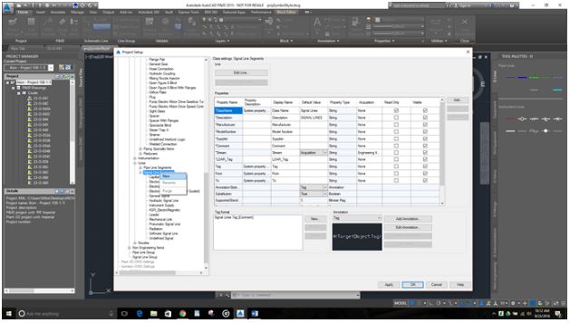
Back in project setup scroll down and expand Lines, expand Signal Lines, right click on Signal Lines and select new as shown:
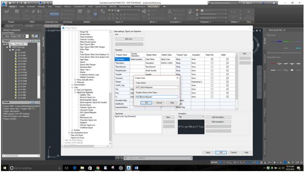
For the name type Ei_ElectroMagnetic, for the display name you can remove the underscore and add a space.
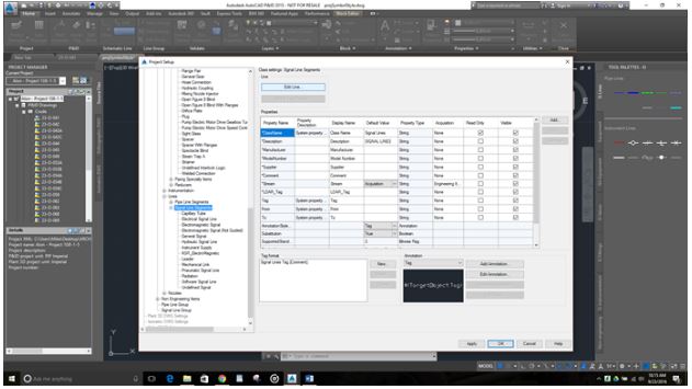
Now select the new Signal Line Ei ElectroMagnetic, at the top of the signal line properties select Edit Line
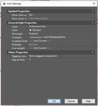
In the window that pops up fill out the properties as shown, for the line type select the drop down and choose your ElectroMagnetic line, after you're done select Ok.
Now in your project setup, right below the Edit Line option for you Ei ElectroMagnetic line, select Add to Tool Pallet, select Apply in your project setup at the bottom right corner, then select Ok.
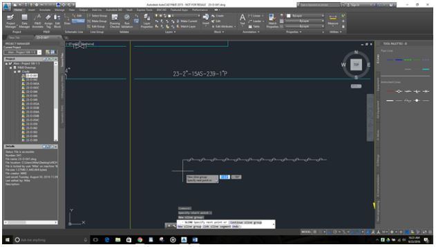
Now open one the drawings in the project using the project manager pallet, select your new Ei ElectroMagnetic line from your tool pallet and draw a line inside the drawing, it should look like this: